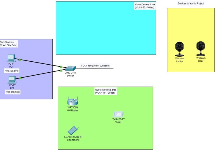
I will now be configuring a guest network and a video network using spare components. To begin, I located a wireless router and placed it into the designated guest wireless network area followed by the smart phone and tablet.

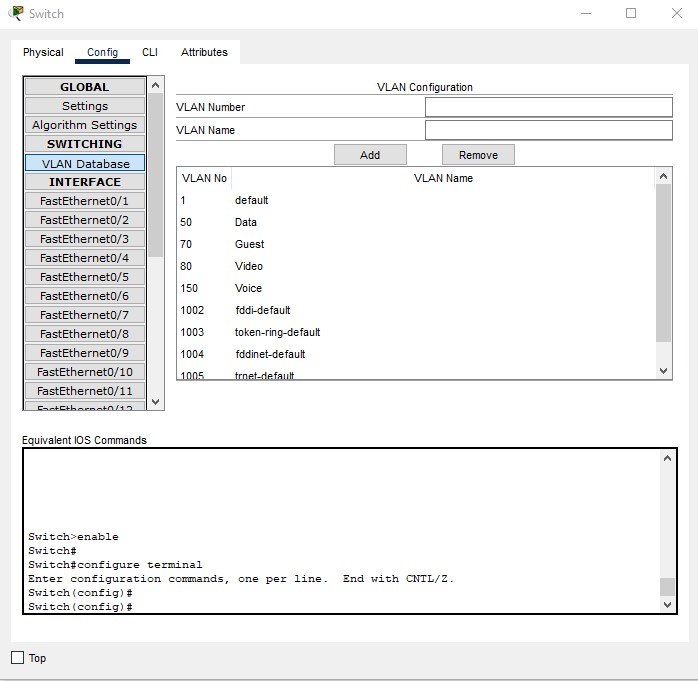
I then will configure the switch for this new network. Clicking into the switch and under VLAN, I will add VLAN 70 to the database and name it as ‘Guest’. While I was in this area, I added VLAN 80 to the database and named it ‘Video’ for a future portion of this project.

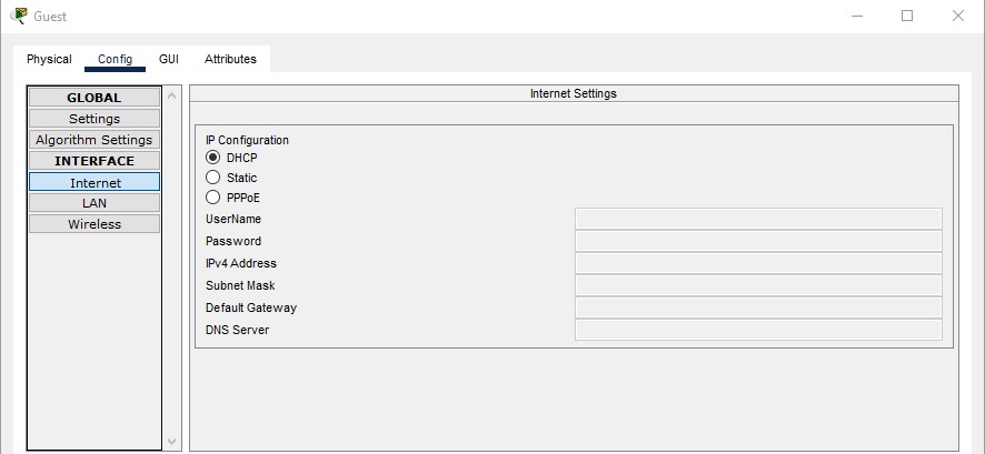
Now I will make a connection to the wireless router from the switch and configure the network. I will now click into the router and make sure my IP configuration is set to DHCP under the Internet tab.

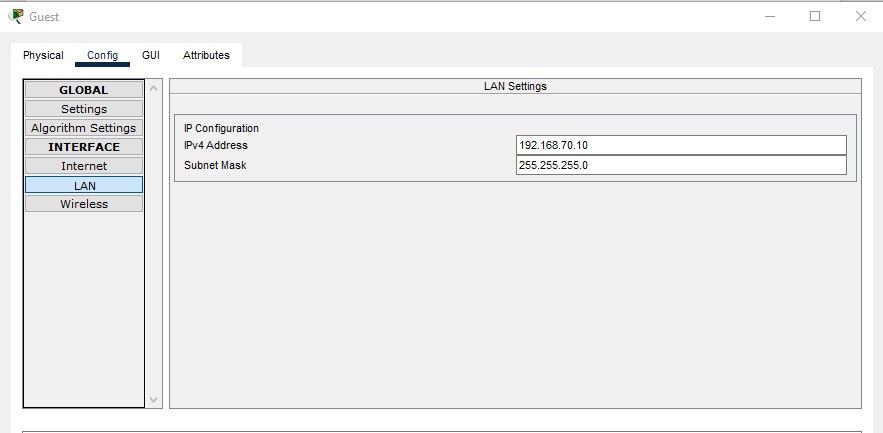
Under the LAN tab, I will configure the IP address to 192.168.70.10.

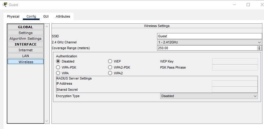
Next in the wireless tab, I rename the SSID to ‘Guest’ and disable authentication.

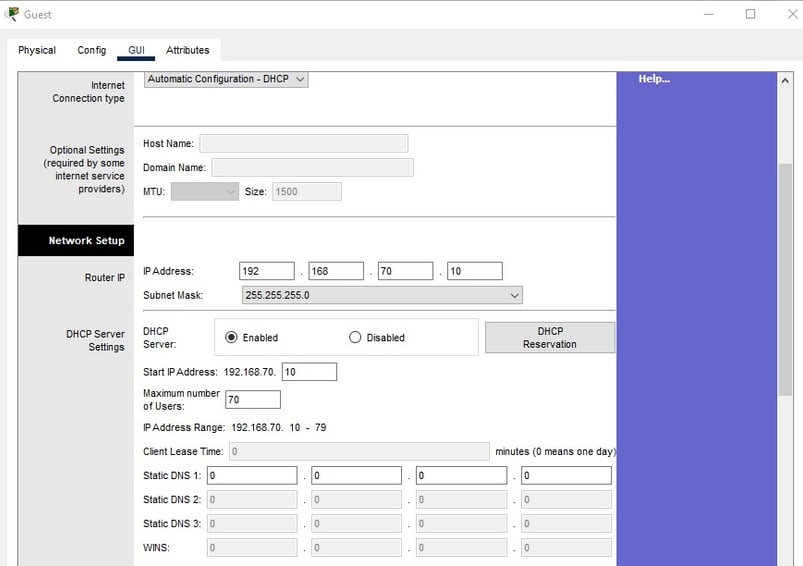
I will then into the GUI and ensure my connection type is configured for DHCP. Then in the network setup section, set the IP address to 192.168.70.10 with a maximum number of guests set to 70. This will set my IP Address range from 192.168.70.10 – 192.168.70.79.

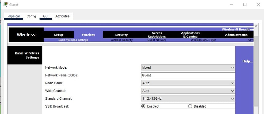
In the wireless tab of the GUI, I set the network name (SSID) to ‘Guest’.

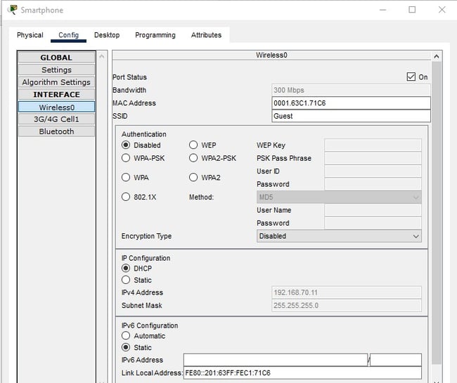
Now, I will configure the smartphone for this network by clicking into ‘Wireless0’ under ‘Interface’ and setting the SSID to ‘Guest’ to match up to the network. I then make sure the IP Configuration is set to DHCP and confirm the IP Address is set at 192.168.70.11.

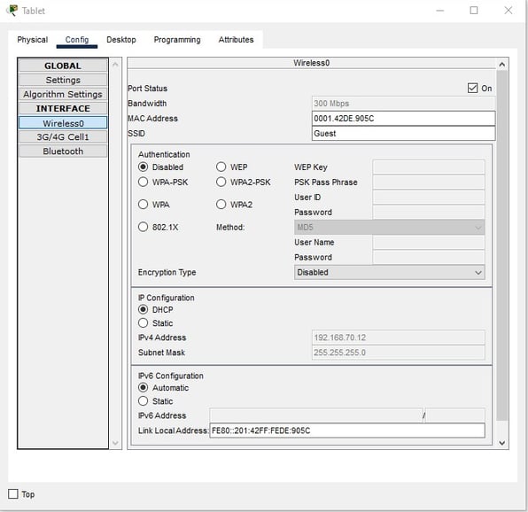
I used the same steps in setting up the tablet as I did for the smartphone with the only difference being the I confirm the IP Address as 192.168.70.12

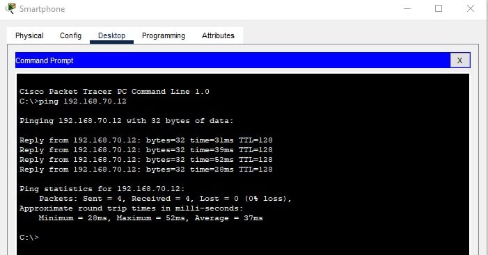
Now that the Guest network is set up, I will ping the connection between the phone and the tablet to make sure that my connection settings are properly configured.
Open the command prompt and type in 'ping 192.168.70.12' and hit enter. If the ping times out, recheck the IP configuration settings.

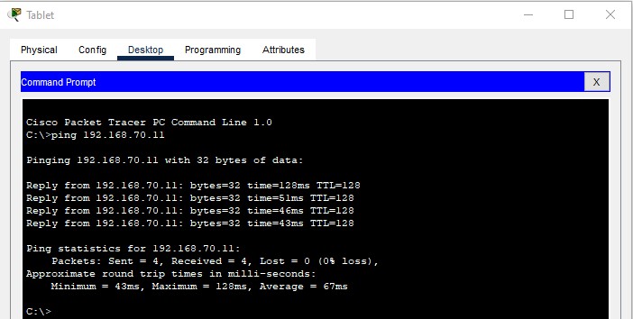

This now concludes the setup of the “Guest’ Network.
Now, I will turn my attention to configuring the two cameras. I first locate and move the two cameras into the video network area. I think make a connection from the switch to the Door Camera using FastEthernet0/1. In config>settings, I set the default gateway to 192.168.80.10.
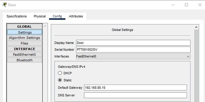

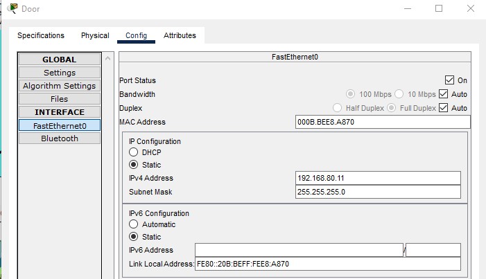
Then go into FastEthernet0, I assigned this camera to an IP Address of 192.168.80.11.

I repeated this process for the Lobby Camera but connected to the switch with FastEthernet0/2 and setting an IP Address of 192.168.80.12.
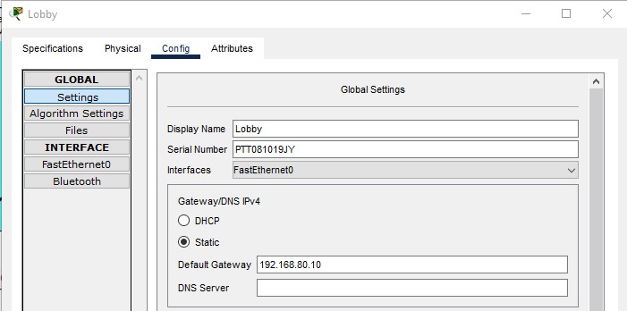

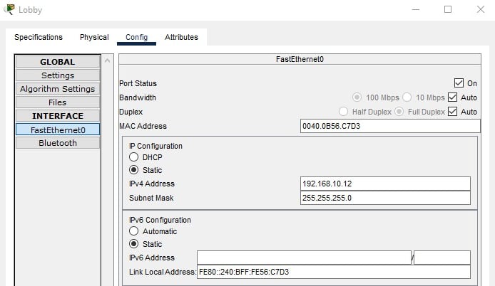

This concludes the lobby and door camera network configuration.
Here is the updated network topography with labels. I made the labels for the IP addresses using the add note tool.
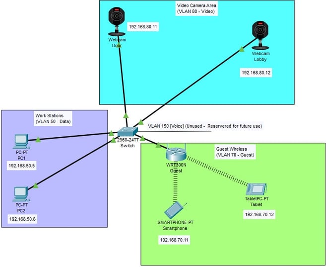

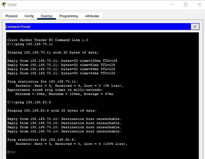
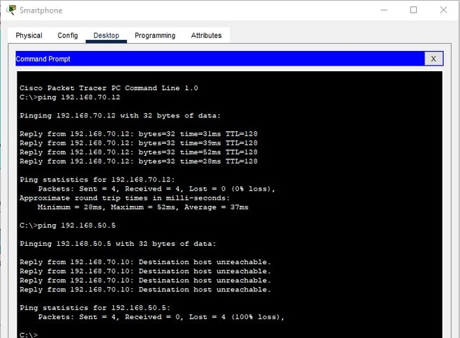
This network is segmented by using separate VLAN’s for the individual networks. The PC’s use VLAN 50, Video Cameras on VLAN 80, and the Guest Wireless network on VLAN 70. Using this configuration enables a more secure network with reduced traffic. Scalability was considered when creating the guest wireless network to accommodate more connections than directly wired switches can provide on their own. With this network being segmented only the devices within their own network can communicate with each other. I have attached the following ping tests to show as much.
Smartphone to PC1:

Tablet to PC2:
